.
.
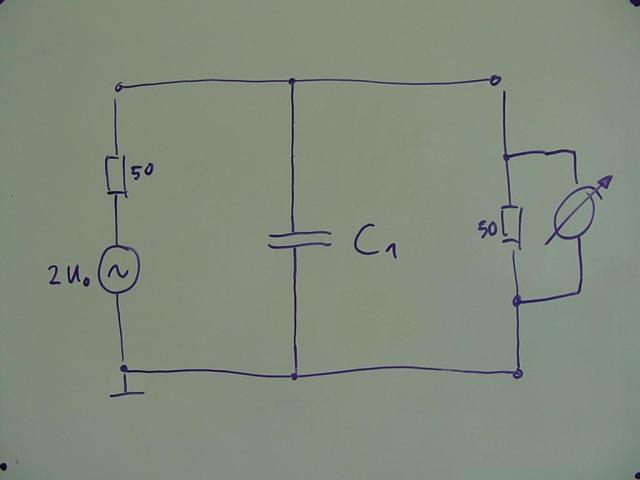
This is a typical filter capacitor inside a measurement setup
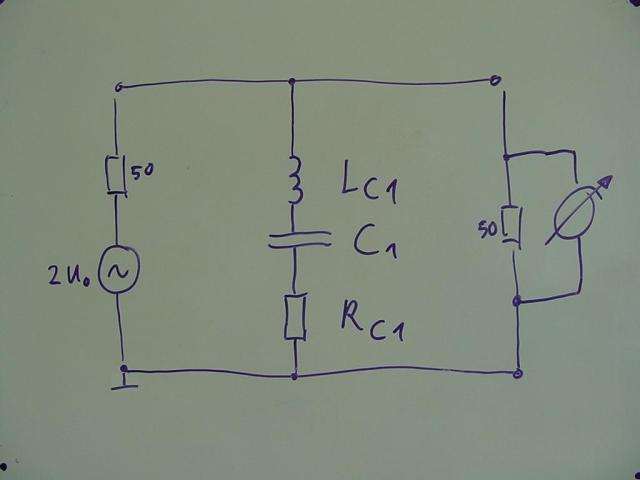
In real life any capacitor comes with an additional parasitic inductance and a real resistance in series,
labeled Lc1 and Rc1 ( = ESL and ESR inside the data sheet)
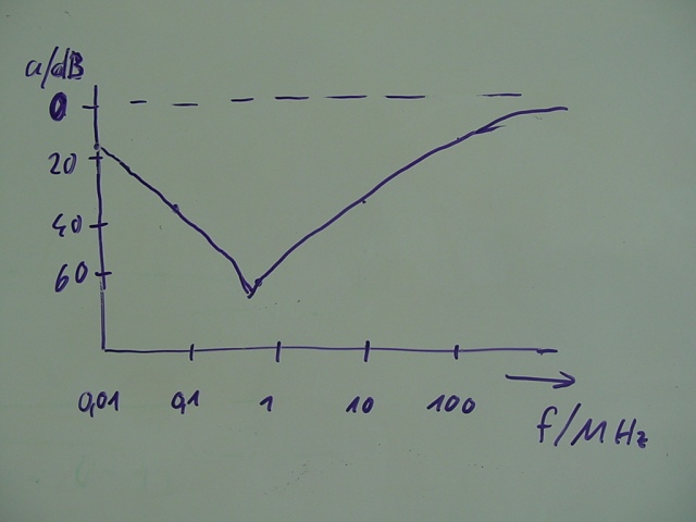
what results in this characteristic frequency response
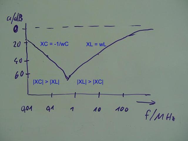
For low frequencies, the reactance of the capacitor is dominant – but above resonance, the parasitic inductance
is extremly disturbing :
There is nearly no more effect from a standard capacitor at high frequencies (> 100 MHz)
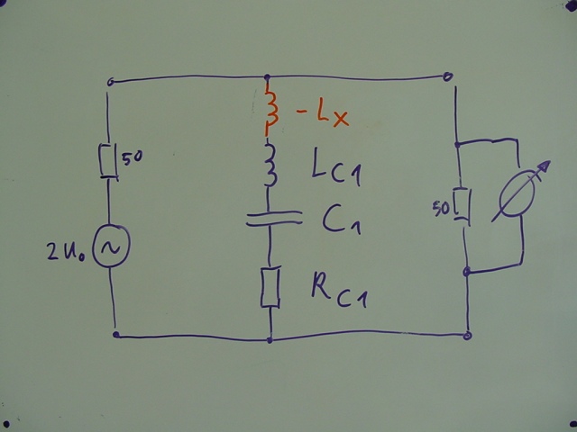
If we could create a negative inductance, equal to the parasitic inductance and in series, both inductances
would cancel each other (Lc1 – Lx = O ) independent of frequency
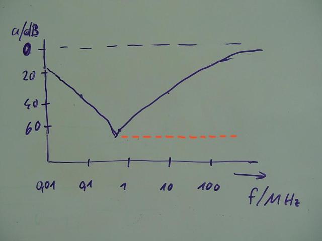
The filtering effect wouldn’t decay above resonance, but instead would remain constant
despite the rising frequency – as indicated with the dotted orange line
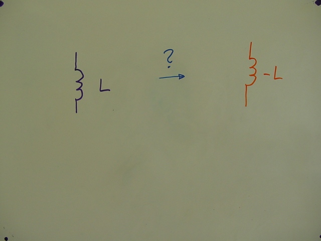
So – how do we get a negative inductance ?
Initially – this seems to be impossible:
passive, absolute, negative devices cannot be built in real life just like that, because they do not
comply with the conservation-of-energy-principle. Negative devices do not spend energy – instead
they would generate energy.
In other words – with such a negative device, you could drive a perpetual motion machine.
So – the question is:
.
How do we solve a problem that cannot be solved ?
.
The answer is – by means of shifting the problem !
.
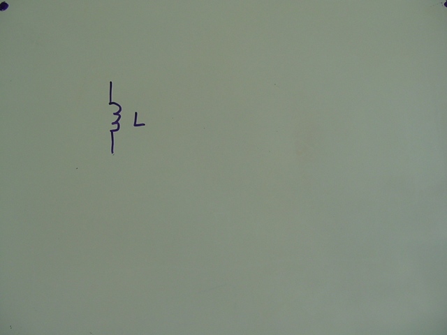
We use a simple ordinary inductance
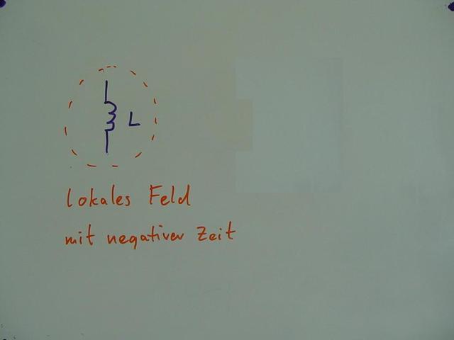
and place it inside a local field of negative time
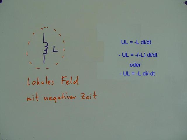
The induced voltage across the inductance L is proportional to the change of current di/dt flowing through
To generate a reversed voltage across the inductor, we would either need an inductor with negative L,
or a current change with negative time : di/-dt
This would result in a voltage reversed to normal polarity.
.
But – how do we generate this field of negative time ?
.
Right – we use a time machine !
.
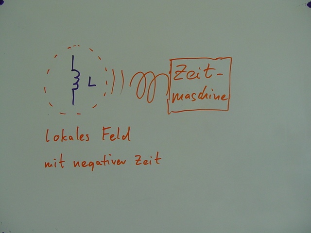
During a time travel into the past the time lapse is negative – the clock is proceeding backwards –
inside the effective area of the time machine, exactly the necessary local field of negative time is being formed.
Well – mission accomplished – minus the time maschine !
Let’s have a look to known time machines :
One of the first versions can be seen in the movie “The Time Machine”
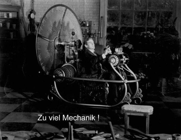
Quite nice – but definitely too much mechanism for our purposes

Still – too complex !
.
.
And this ?
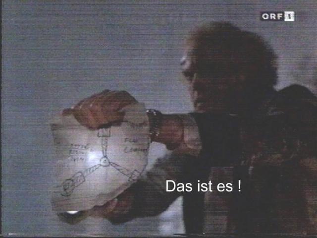
That’s it !
The Flux-Capacitor ! (= Flux-Kompensator)
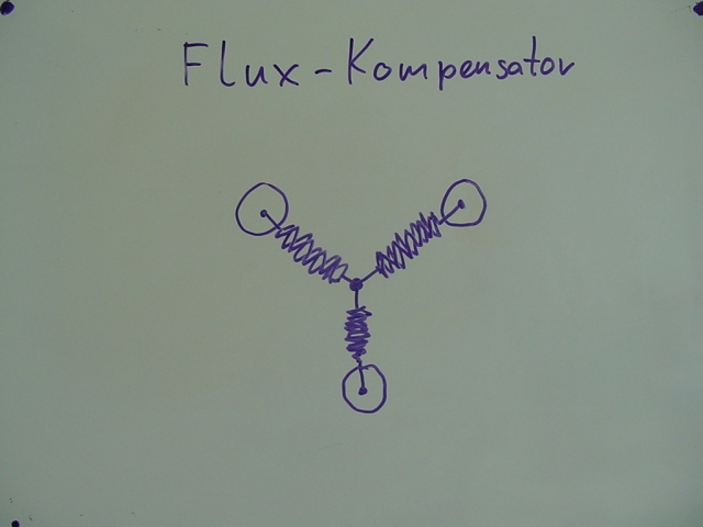
Capacitor in this context is less referring to a capacitor device
but to its capacity of handling flux
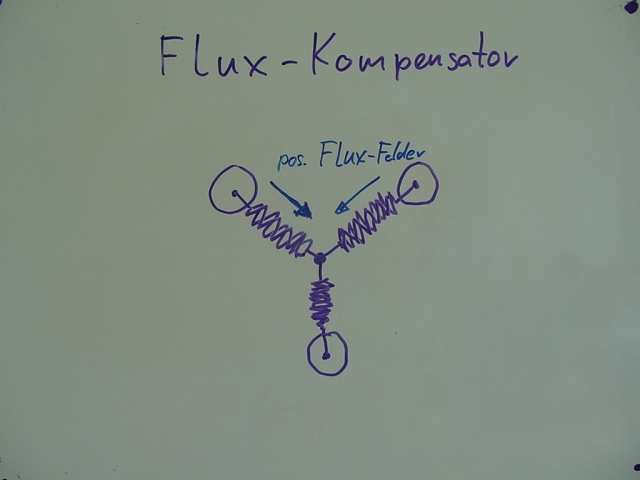
If 2 of the flux elements are being excited by positive flux energy…
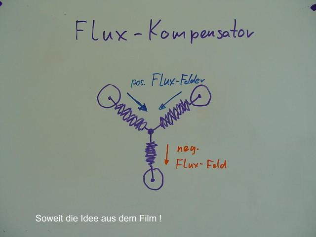
… there will come out a negative flux field across the 3rd element – generating the negative time !
So far the idea from the movie !
.
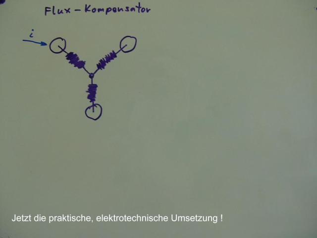
Now – the practical, electrical realization !
We supply current (i) to one of the connections of the flux capacitor
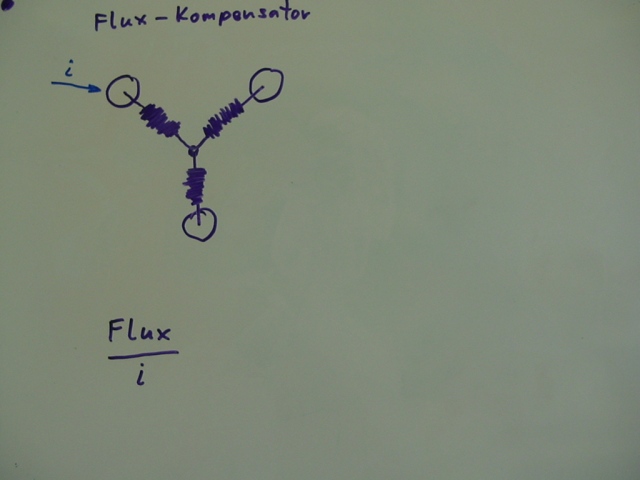
thus causing flux inside the element – Flux / i
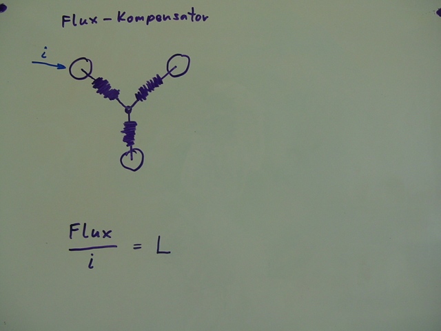
The ratio of generated flux per current i we define as L
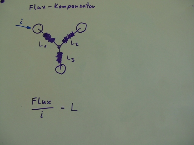
For each element of the flux capacitor – L1, L2, L3 accordingly …
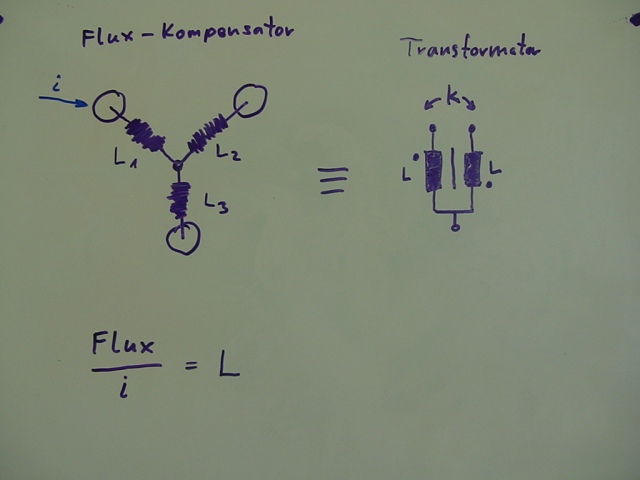
… and suddenly realize, absolutely perplex – the flux capacitor is identical to a transformer !
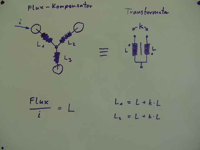
The conversion of L1 and L2 follows the above given formulas …
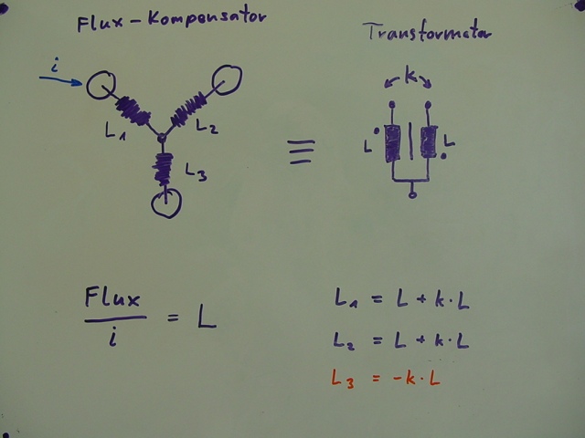
… and – this is the point ! – L3 becomes in fact negative !
We built a passive, frequency-independent, negative inductance – using a time machine !
You don’t believe it ? Everything is correct !
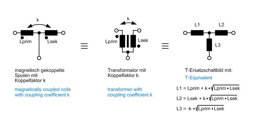
For the experts – all the necessary conversions and formulas as overview
.
.
This is how a handmade negative inductance looks like in reality :
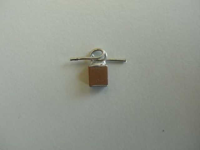
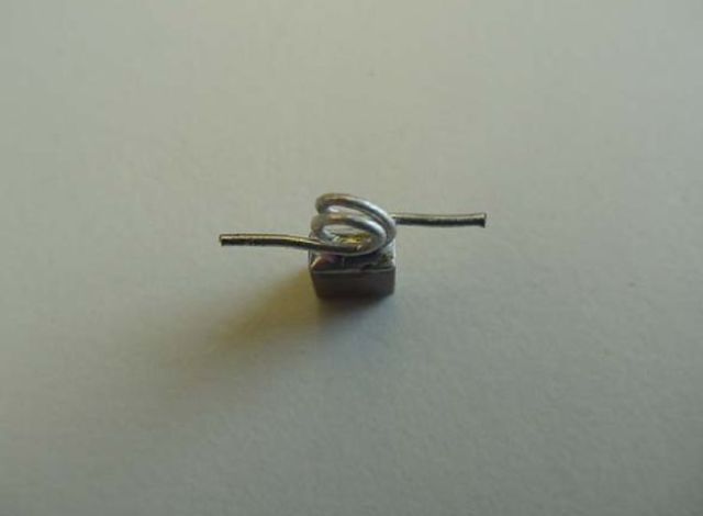
The capacitor is soldered to the center tap of the coil.
The area of the turn (inductance) and the distance between turns (coupling coefficient k) is such
as to generate a negative inductance at the connection to the capacitor, which is exactly of the
amount of parasitic inductance of the capacitor.
You can easily imagine the difficulty to accomplish this by hand (taking into account the tiny
dimensions) – so, normally you will have a deviation of about ±10%.
But even so – the result is impressing and amazing.
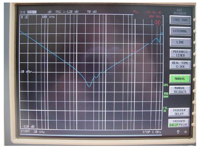
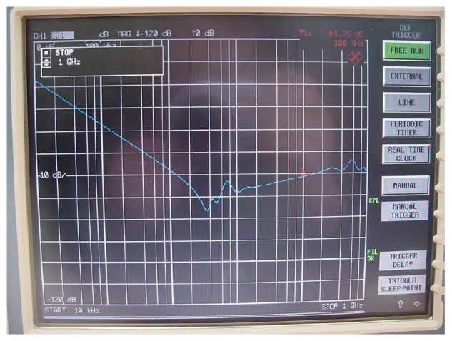
.
Addendum
The method of building a negative inductance, was widely unknown until recently – though the physics
(transformer) and the corresponding formulas had been taught and applied since over 100 years.
However -asking what to do with negative results from calculating equivalent networks , students regularly
heard the reply, they could not use this – because there were no negative devices in reality !
And many people still believe so !(classic interpretation of negative inductance)
In fact – it is the other way round ! If the equivalent network results in a negative device – the real
network behaves as if there was such a device really present – though being invisible.
For additional information see to Filter using Negative Inductance
.
Just for fun – google for negative inductance and look what you get !
Or even worse – google for negative Induktivität and see what you get then !

Simulation looks very interesting. Will it work for a circuit down at the VLF frequencies? Up to now only active circuits have been used for the VLF.
Comment by Dennis Kozakoff — 18/07/2009 @ 20:47 |
This concept of building a negative inductance is per se frequency-independent.
Normally, there is no big deviation between simulation and reality, as long as
your components and parameters are linear and set correctly and you don’t have too much
stray effects.
This means, that you might get problems if you wanna use magnetic core coils instead of
air coils and air coupling, because the coil and coupling parameters of magnetic core
material is not fully linear and may also vary with frequency and temperature.
Due to stray effects, skin effects etc. the simulation may work for a foil capacitor like
in the simulation example up to 100 MHz. For the ceramic capacitor in the picture
the principle did work well up to 1000 MHz.
Comment by 4gang — 18/07/2009 @ 21:51 |
Oh, i forgot – i like your illustrative approach above, BUT i still cannot see where you got the MINUS (-) sign from in your derivation for L3 = -k…! Can you please show us where it came from?
Comment by Glenn Roberts — 20/06/2010 @ 16:28 |
Glenn – the minus sign for L3 is simply a consequence of the T-equivalent for a transformer.
I had been inspired by the striking similarity between the T-model and the flux capacitor for this
funny and stunning derivation (of negative inductance).
Some more insight into this idea you can find in
and more insight into the technical background you will find here
Heinz
Comment by 4gang — 20/06/2010 @ 17:34 |
Glenn,
I will phrase your question back to you: Where did YOU get the minus sign? Was it because someone taught it to you that way when you were an undergrad?
The conventional equation for an ideal transformer is wrong and people have been fooled into believing an incorrect solution for over 100 years. I have evidence of this at VLF frequencies and the implications are big. 4gang is correct and a time reversed magnetic field does exist.
Comment by Jules — 02/07/2010 @ 21:40 |
Hi 4gang,
Can this negative inductance be scaled up say, to reach the size of a rather big coil with Litz wires and an ultracapacitor? Will the negative parameter be so big as to affect the time-space of the space inmediately adjacent to the negative component??
What are the direct and practical implications of a modified curve of frequency response of a negative inductive device?
Comment by aaron5120 — 22/06/2010 @ 12:19 |
hi GUYs
To help this subject, I have a few scans of a work by Brailsford on such things as negative permeabilty (=> inductance) with graphs etc showing true negative values at certain frequencies and field strengths!!
If you can provide a way to upload a few pictures here – i will share it with U
Glenn
Comment by Glenn Roberts — 01/07/2010 @ 02:36 |
would you provide drawings how did you connect capacitor with soldered coil to the network analyzer?
Comment by Henryk — 26/07/2010 @ 19:22 |
Reading blogs in general bores me and it’s hard to catch in all this, if you do not follow up a blog from the beginning. Unfortunately, blogs, mostly with what we have to do is just boring and not very transparent, so you can very quickly discouraged. Therefore, I stopped for some time be interested in what people place on their blogs. But appeared in the Internet space, this blog has completely changed my approach to this type of service. There are no boring thoughts on it on trivial subjects or superficial articles that talk about nothing. If we are interested in precisely this theme, it’s worth a look at this blog and read. I am very surprised that so interesting you can solve the same graphics and layout of content. Such steps make it a blog is very clear and readable. His coloring is friendly to the eyes and spirit. Of course, many people could now resented and recognize that it is not that important, but if you spend on the internet a bit more time and read more, you will surely appreciate the fact that an appropriate image, which does not strain our eyes. Therefore, even if the color of your blog are of great importance, which is discovered in time. This blog I discovered not so long ago, but immediately interested me. At first it was curiosity about the same form, layout, content and divided into categories. However, when I began to read. It turned out that this blog conceals a much more interesting content than might be assumed at the beginning. This blog though it looks like a typical blog with better graphics, after all, a little different from the other pages of this type, which I have visited. First of all, because the information that you find here are really valuable. In other sites, you can often find the writing for the sake of writing, because in such cases only wasting time. This blog breaks away from the trash, so that only people who are really looking for information, may be interested in it. Keep up the invite to your blog pozycjonowanie stron
Comment by pozycjonowanie stron — 13/12/2010 @ 00:48 |
A great post, thanks for taking the time to share, continued success to your site in the future!
Comment by Burton Haynes — 23/01/2011 @ 16:55 |
WONDERFUL Post.thanks for share..more wait .. …
Comment by Tetris — 10/02/2011 @ 03:10 |
Right on!
Comment by cevon — 21/07/2011 @ 02:48 |
Its wrong to use normal language in electrical terms to maths as negative is the reverse co efficiency of normal current and I do have a powerful free energy negative induction technology .The super flux cap is also a miss conceived math formula as it can not act as a negative field in a co efficient way unless its materials are also chosen to fit that equation ! Its also important not to use the same approach as a point of study as we would in normal electrical engineering as the time variable over resistance does not apply and ohms law is no longer included .
I can make a simple coil negatively charged by altering the internal position of electrons to one side of that coil ! So we get a 100% compressed to one side of the coil and than super pump the coil with electrons ! The mass electrical charge of the coil becomes super negative by up to 10 000 % … Thats enough to levitate the coil and throw it into space …… Interesting diagrams but its best to
start from fresh with a new language and formula to express the so called negative term but to be honest its neither negative or positive it more a shift of pressure inside a solid state atomic vacuum ! It make me wonder how such a simple reality is not considered by the likes of NASA ?
BUT BE WARNED ! there ARE MANY risks in this energy type as all surrounding matter and possible time can be affected including gravity but not atomic nuclei as they are to close to the mass of the earth and there quantum relationship would only change if one was to apply the same amount of energy as to the atomic mass of the earth so forget negative mass ……. its impossible ! But negative co efficiency as an opposite effect to a positive EMF of resistance is a reality and is seen as the reason why galaxies are accelerating away into the inflation of the universe ! But that is another side to this energy and I do mean energy …..
Comment by michael richardson — 19/11/2015 @ 23:20 |
Ok, so there IS a theoretical way to create a negative inductor (which can violate the CoE). Consider a negatively charged disk rotating, it deflects a compass as the moving charges create a magnetic field due to the relative motion between the HV neg. electrostatically charged disk and the Compass. Ok, so what if we move the compass around the stationary disk? Relativity insists that relative motion is relative motion, so it should feel a field as the compass sees the disk moving relative to it. But the magnetic field is not seen by us in the stationary frame, if we change the direction of rotation of the compass around the disk the field the compass sees flips. If the compass was an electron, what would it see as it accelerates? It would not see the magnetic field from it’s own motion as it isn’t moving relative to itself, it would see a magnetic field from stationary disk, ad in would be speed up in it’s acceleration around the disk, it would see negative impedance. An electron in a wire seems the protons as moving and see the magnetic field from that growing, but if the wire was negatively charged and bifilar, it would see negative induction!
Comment by John — 04/11/2016 @ 03:53 |
John, the concept of a wire with a scalar charge generating a negative impedance is something I saw in another device but I am not clear on the explanation.
> Consider a negatively charged disk rotating, it deflects a compass as the moving charges create a magnetic field due to the relative motion between the HV neg. electrostatically charged disk and the Compass.
Lets consider the Lorentz Force (F=VxB). It describes a relationship between a velocity, magnetic field, and force each 90 degrees to each other. If we consider just the magnetic field (B-field) from the rotating charged disk then we can replace it with a magnet. The direction of the magnetic field is through the disk. If we have an electron circling the disk then the right-hand rule tells us that it will see a radial force either toward or away from the disk. The charge would apply an additional radial force (E-field).
The key point here is that the forces work just like a gyroscope. A force applied on the electron around the disk is translated 90 degrees. We have a balanced action/reaction except that the reaction is 90 degrees to the action. If the electron is traveling through a wire around the disk then it would be pushed to the edge of the wire but the effect would be negligible. The B-field of the electron really does nothing here because the electrons quickly align or polarize with the surrounding B-field but as the electrons move around the disk they will generate another field parallel to the one created by the disk.
> Ok, so what if we move the compass around the stationary disk? Relativity insists that relative motion is relative motion, so it should feel a field as the compass sees the disk moving relative to it.
The Lorentz force can also address this case if we consider the the variable F as the force between the electron and the disk because of the E-field. The F is radial, V is around the disk, and B would be through the disk as before. This B field would be the field seen by the electron because of GR.
> It would not see the magnetic field from it’s own motion as it isn’t moving relative to itself, it would see a magnetic field from stationary disk, ad in would be speed up in it’s acceleration around the disk
The above statement is the one that seems incorrect. The F is radial and not around the disk so there would be no acceleration through the wire. As before the force would be on the edge of the wire but it would not do anything. This is similar to the skin effect where electrons are pushed to the edges of a wire at high frequencies.
Comment by chadj2 — 12/11/2016 @ 22:18 |
It’s a while since I wrote that and forgive me for not getting a better handle on it, but let me put another way what I was trying to say. Let’s sat there was train and train track. The Train is negatively charged and the track is positively charged. if you are standing on the tracks, do you see a magnetic field from the tracks? No. If you are standing on the tracks do you see a magnetic field from the negatively charged train moving by? Yes. It you are on the negatively charged train do you see a magnetic field (remembering all reference frames are equal) from the track which you are moving relative to? Yes. Do you see a magnetic field from the train which you are stationary relative to? No. Ok, so what if the track and the train are both charged negatively??? The train never moving relative to itself would never feel a magnetic field from itself, it would see a magnetic field from the track, as the train accelerates that magnetic field from the track would seem to grow in strength, and thanks to Lorentz we can see that it would place a force on the train, what direction is this force? Turns out, it will assist the acceleration!
Comment by John — 07/03/2017 @ 22:59 |
I have a powerful negative free energy generator ! It best to dump the tex books when looking for free energy and with negative energy you need to include time as a force and mass as its partner charge in this respect or a magnetic field is not the important factor ! Negative drop permits velocity of both electron spin and the gain in mass for the electron as it gets closer to light speed.
If you consider that time of one second is divided into the mass of an electron and an electron in a negative state moving towards a positive state we get a gain in velocity and that can result in gain in output.
Time is related to distance try this very simple experiment with 3 dc 22000uf 35vDC capacitors as they are stable at 25vDC …….. Just set them out like this where C is the capacitor !
+C 1- +C 2- +C 3- This separation as distance between capacitors is mostly missed out in normal circuits but its a very important effect when set out like this as you get a small 10% rise in the output volts !
You can observe the electrons accelerating in quantised steps between c1 c2 c3 and we know electrons are quantised when jumping between energy levels and we can permit that to happen just by setting out the capacitors in the same way but with time over distance ! Also in 5ths along a harmonic root in chromatic order… This unifies the speed of the electron to the harmonic laws of chemistry light and sound !
Then we can increase this when we learn to charge up a coil to a negative state where all the charged electrons occupy only one side of the coil ! I tend to keep that bit a secret but what it does is to propagate virtual electrons to occupy the overall gain with more electron mass when we keep increasing there speed to light speed ! The wont go beyond the speed of light and if you teach them to try and achieve that they just produce more and more virtual electrons …
Simplicity is the only way to fully understand free energy and as you can see you only need 3 capacitors to learn that with ! I am a master of this kind of free energy effect as I invented it !
I now only use harmonic laws of the unified fields that all energies resonate with ! I don’t even use the term volts or amps or ohms laws and lenz law is not considered in any of the equations ! Its just to far outside their box of mathematics that only define the box as laws of limitations yet the universe in not limited to any of their laws ! So why bother with them ?
I can do everything from free energy to invisibility to zero gravity mass to worm holes and much more as I don’t permit limitations to entre the formula and just go with my own set of rules that to me are the real rules by which constructs all that is !
I am here to help !
Regards
Me
Comment by michael richardson — 13/11/2016 @ 02:39 |
> Negative drop permits velocity of both electron spin and the gain in mass for the electron as it gets closer to light speed.
I am not sure how you are getting relativistic electron speeds in a simple circuit. The typical speed of electrons through copper known as the drift velocity is on the order of mm/hr. (see https://en.wikipedia.org/wiki/Drift_velocity)
> You can observe the electrons accelerating in quantised steps between c1 c2 c3
The only way for electrons to travel through space in an open circuit is arcing which takes much more than 35V and tunneling which requires a distance small than the width of a human hair.
> you get a small 10% rise in the output volts
If you have an open circuit showing a voltage it means that no current is traveling though the circuit.
> Its just to far outside their box of mathematics that only define the box as laws of limitations yet the universe in not limited to any of their laws ! So why bother with them ?
The discovery of most physics was preceded by the discovery of the math to describe it by about 100 years. In the case of Newton he invented the math required to describe his physics. In the case of Maxwell he used math to prove light was made of electromagnetism. One of the things I am investigating is how math can show how the holographic principle and Hubble constant can calculate the masses of the proton and electron. You can’t get much done in physics without math.
Comment by chadj2 — 20/11/2016 @ 23:22 |
Hello chadj2 ! sorry for the delay in responding to you . I will respond much quicker ! Electron mass is formed from a point in time known as the big bang but before the bang only time existed suspended between past time present and future time … Then bang ! Mass can only exist if formed from nothing if time is condensed …. ELECTRONS QUANTUM JUMP ! And one can safely say that there is only one electron yet it seems like its many almost everywhere at the same time …
The terms electron drift that flow in the opposite direction to the flow of current and electron speed require an additional term as the jump speed or the Q S speed of the jump …… VERY IMPORTANT !
Negative drop say at the cathode is when electrons drop form one side of a coil to the other causing an imbalance creating a gain in pressure ! This is a free energy gain !
The spin of an electron at 5.5 million mph for a free electron at rest at say -13.7 Ev at its lowest quantised charge is also a unified number over the age of the universe …. It will change when the universe is a perfected 13.8 billion years old ….. Any mass out side that change comes from a multi verse !
Best to use this as the anchor for a unified electron field over time and one needs to understand the maths of quantum jumping electrons and to do that you need the numerological constant ……
Other things to consider is calculus needs an up grade over the number one …… 1 and the new number is 1.01 ! 0.1 is a reflection of its quantum state …….
If you require the know how as to form a negative coil let me know and I am happy to let you have that … I invented it !
Keep it simple and very few limits including new forms of math ! You may also need the numerological constant and the unfed field so I will let you have that to …..
Regards
Michael Richardson
Comment by michael richardson — 07/03/2017 @ 20:11 |
> Mass can only exist if formed from nothing if time is condensed.
What creates mass? Many people would say “the Higgs” but there may be a simpler explanation. What happens when an electron accelerates in free space? You see a moving charge and so it builds a magnetic field around it and that takes energy. One can conclude that at least some of the inertia was caused by electrical induction and therefore at least some of the mass is a direct result of an electromagnetic effect.
The trick is to show how this happens with particles that are not charged but don’t all charged particles have mass? An atom may not be charged at a macro scale but there is internalized charge. Another problem with this explanation is that particles of the same charge have different masses but there may be a similar “trick” to this as well; however, the electron is the simplest case and so the key is to understand it first.
What does this say about gravity? The electric and magnetic fields around the electron contribute to its mass and therefore also contribute to its gravity field. All sorts of things create gravity including electromagnetic fields, dark matter… actually any kind of energy (since energy is equivalent to mass).
> Negative drop say at the cathode is when electrons drop form one side of a coil to the other causing an imbalance creating a gain in pressure
So you are saying that electrons jump from one coil to another? The magnetic field creates an EMF that creates a current in the other coil but I don’t see how any charge is moving between coils.
> Keep it simple and very few limits including new forms of math !
One of my areas of study is new forms of math (at least relative to the mainstream). When Paul Dirac chose to use gamma matrices (https://en.wikipedia.org/wiki/Gamma_matrices) to represent his QM theory (https://en.wikipedia.org/wiki/Dirac_equation) he made a breakthrough but he created a system that was unintelligible because it covered up the fact that he was really working with Clifford multivectors (https://en.wikipedia.org/wiki/Multivector).
Physicists were able to calculate results from his equations but they were locked into an unnatural system of math that limited what they could do and understand. I think this problem still persists today and we are limiting our possibilities to interactions on lower subspaces of the Clifford algebra. Many physicists will admit that while the math works they don’t know why.
In 4D space there are a total of 16 basis blades that make up the Geometric Algebra (https://en.wikipedia.org/wiki/Geometric_algebra) system. These are the full set of vectors we need to understand spacetime. For example if you consider all the ways that smoke can pass through a point you will need no more then 16 real numbers to fully describe the motion. These 16 numbers give you the COMPLETE PICTURE.
Angular and linear momentum can be interchanged but we need a system of math that explains how and under what conditions. So let’s convert some electron spin into linear energy 🙂
Comment by chadj2 — 01/08/2017 @ 04:28 |
I fully agree !! Linear energy is a constant of the unified function yet one has to include the octave !!! 12 !!! The number of 16 for me is 4 sets of vectors in the 12 note octave but a chromatic scale is 12 its interesting that 16 can be also 1+6 =7 The number 7 is the number of notes for all major minor scales and for a linear scale we need the number 13 as this connects two octaves together where say A is the first and found at the 13th ….. So now we can see that 16 is 4 sets of scales for the electron in a 13 note octave …..
The scale for quantum jumping for me is a 9 note scale for me to detail the 9 I would have to send you a copy of some of my work in the harmonic laws of how a 9 note scale can be constructed from a combination of MAJOR MINOR scales … I make a square 12×12 box chart of a 12 note octave where each scale is one colour and the gaps between the notes present how the electron jumps with in the octave ….
One can also determine the perfected position for electrons by this as long as you know where the 1st electron position is and it complelty destroys the uncertainty principle for the location of where an electron is … haha even in a slit electron experiment as long as the reciver is boxed out as a 12 or 13 note grid and you map the position of the first result you can map out all the other electron positions …. The Harmonic grid is considered as moving at a speed equal to the speed of the solar system at 750 000 mph = 7+5+0+0+0 = 12 haha
Now to me that equates electron vectors available to that number at one unified moment of time where time is condensed into one second spread over a 2D plain as the fabric of space time …. The plain is also bent at 2.2 degrees as space time curvature so if we want to map out the position of the electron in a slit experiment we need the reciver to also be bent at 2.2 degrees or the electron position can not be determined as the experiment slit reciver would be flat and the space time is not flat …..
I have a special coil arrangement for the collection of free energy electrons or you can call them virtual electrons ?? And again I would need to email the schematic for that arrangement … In simple terms its a two sets of coils on a drive shaft set between two 3 phase AC generators and worked buy a circuit contact between a large cap bank where the centre point between the two coils is the point of contact in the circuit and produces above unity results …….
Electrons are jumping into these coils yet I am not completely sure where from ??? But from here I want to limit the number of possible vectors for an electron to 75000 that sit inside a 12 and 13 note octave … This makes it simple and is unified to the harmonic response available in the octave …..
I want to also set time to the same numbers and use the electron as a unit of time where charge is set as a 5 note pentatonic scale equal to the 5 quantised states for the production of photons produced when the electron in in charge and in release of the charge … 5 is also the 5 black notes found on the piano ! As sharps and flats ect …….
The universe should also be seen as one electron where each galaxy is sharing this electron linear field and as we look at the stars in the sky a comparison to the electron slit experiment is considered where each star is like a received position found on the reciver ect ……. I want to also limit the number of dimensions to the number of 12 for a 4 dimensional chromatic grid yet a 13 note would imply the first note of a completely new universe one octave up from our universe …..
The above sets the research firm into harmonic order !!! I have some interesting experiments with affecting gravitons of objects around a contact transformer connected to a cap bank where on contact these objects jump up …… The objects need to be fixed into a chromatic position where the transformer is in the centre …… This is like a Hutchison effect but using only 36 v as a unified number for a 36 billion year time line for protons…
36 = 3+6=9 so the agreed life time of a proton at 36 billion years is now used forming a 9 note scale over gravity !!! If I point an increasing scalar frequency set to 9 18 36 72 144 and so on at any mass at a certain depending on the number of protons in the mass gravity is affected for the target mass object ………………….. Again the linear field applies where charge in that field is inversely square within the field meaning that there is no loss of energy over the length of the field….
A 12×12 grid is 144 and the numbers 9 18 36 72 144 relate to the 5 quantised states for the electron the corresponding electron vectors of the 5 states would in my point of view fluctuate between these number at a ground temperature for mass at -273 c = 2+7+3= 12 haha again the octave !!
When we work with a 13 note octave where we see the note A set between two octaves , example A – – – – – – – – – – -A we now begin to form a string between two points in space time and for me is why a lot of quantum mechanical effects can take place … Each atom is can in one sense has this string between them !
If I made two pendulums and sent you one where an atomic clock was to release the pendulums at the same time and I began to slow my one down your pendulum would also slow down hahah do you see my point ??? haha
Theory is one this experimentation is another but fact over fiction determined by simple laws of harmony creates a very special tool box !!! Your going to need one sooner or later …..
Regards
Michael Richardson
Comment by Michael Richardson — 09/08/2017 @ 22:06 |
This site is just gret. I’ve researched these info a great deal and I
view it that is good written, easy to understand.
I congratulate you for this article that I’ll tell to people friends.
I ask you to visit the gpa-calculator.co page where each university student
or scholar can calculate ratings grade point average levels.
All good!
Comment by Odette Wenderoth — 31/03/2018 @ 17:46 |
I have crazy idea of using hub dynamo (shimano 6 V, 3W) on my bicycle not only to power lights but also to brake at least a little. Of course, 3 watts is unnoticeable at all, I want it to take out at least 50 watts, or even more! Everybody say it’s impossible: it’s just too weak. But what’s interesting: its active resistance is small indeed, 3,5 ohms. Its voltage without load is also pretty good: I got up to 44 volts rectified (with 60 mA load) when riding up to 30 km/h.
So if we only had active resistance and short-circuit this generator, it could draw almost 280 watts when riding at 30 km/h, or 115 watts at 20 km/h – not bad at all! (hope its winding has some thermal inertia to withstand these powers at least for couple of seconds).
But leakage inductance of this dynamo ruins everything! It is specially designed to limit current to 0,5 amperes, no matter what velocity one drives. Higher the speed – higher frequency and impedance of this inductance. That was great for light bulbs: they have nominal power no matter the speed. Very ingenious design actually.
I did experiment with connecting capacitor in series with this dynamo: it indeed increases power output, but it is effective only at one specific velocity (and hence frequency) where resonance occur. So what I need is high-power negative inductance, so they would cancel each other out!
That’s how I got to your site 🙂
My thoughts are: negative inductance should not violate conservation of energy because it is still reactive component, it doesn’t generate power and doesn’t draw it, just pushes it back and forth. But how to accomodate your circuit to this hub dynamo still eludes me…
Comment by Yuriy — 15/05/2019 @ 17:24 |
Hallo Yuriy,
Phantastic idea – but I’m afraid you have to use a configuration like depicted above with coupled coils – in order to get the negative Inductance. And I don’t see, how you could apply this to your dynamo.
Sorry – I can’t help with this.
Viele Grüße
Heinz
Comment by 4gang — 15/05/2019 @ 17:58 |